
This article deals with adding a push button on the Raspberry Pi’s GPIO pins and writing a daemon that handles push button events. If we press the push button for less than 2 seconds, we want the daemon to shutdown the system and if the push button is still depressed for 2 or more seconds, the daemon must restart the system. First we deal with the hardware part of the problem.
Things to know:
- Raspberry Pi has a 3.3 V microcontroller which means 3.3 V is considered logic high
- The GPIO pins do not have voltage/current protection, so working voltage must strictly be 3.3 V and current in individual pins must be less than 16 mA
Wiring up hardware
Before we can wire up the GPIO pins, we need to convert the male GPIO pins on the board to female. According to the internet, an IDE hard drive cable is a good candidate for this. Unfortunately, I couldn’t find this cable in my local electronics shop so I settled with the following connector.

I did have to bend the pins a little on the connector so that it grips the GPIO pin well. Scroll down to see how the connector fits on the GPIO pins.
If you are new to electronics, wiring up the 3.3 V source on the board directly to a GPIO pin and putting a switch between them seems to be a no brainer. Unfortunately, this has two problems. First, if an accidental short occurs, a source voltage directly connected to a pin can cause large surge of current – damaging the hardware. Raspberry Pi’s individual pin is rated to work with current less than about 16 mA. We want to keep the current well below this limit. To solve this problem, we add a resistance big enough to limit current.
Secondly, when the switch is open, the pin is in what’s called a floating state. This means that because the pin is connected to neither a voltage source or ground, the input pin is in an indeterminate state. During this project, I once incorrectly wired the circuit to leave the input pin as floating. When I pushed the button, the program would correctly read the pin value as high because it was tried to a 3.3 voltage source. When released though, the program would still read high. But if the program was asked to read the pin a second time, then the program would correctly read low. This strange behaviour is caused by a floating pin.
To avoid this problem, we need to configure our push button circuit such that the pin is driven to either ground or 3.3 V depending on the state of the push button. This is done by using a pull-down resistor. We use a ‘pull-down’ resistor to pull the input pin to ground, when the pin is disconnected from logic high voltage by the push button.
Hence, the following circuit diagram shows the final setup of the circuit for GPIO pins:
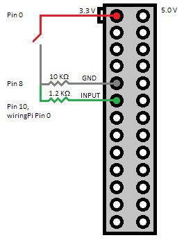
From the wiring diagram, we can see that when the switch is open, the input pin is connected to the ground. When switch is closed, the 3.3 V source is parallel to the 1.2 KΩ load which means input pin will be at 3.3 V (because the source is connected in parallel to both the loads). The 10 KΩ resistor is the pull-down resistor while 1.2 KΩ resistor is a current protection resistor. Using the consequence of Ohm’s law – Voltage = Resistance * Current – we can calculate that when Voltage = 3.3 V, using the resistance values used above gives us a current below the rated limit.

 Wiring view
Setting up software
‘wiringPi‘ is one of the most commonly used GPIO library for Raspberry Pi. Setting up this library is detailed in the library’s website.
Assuming you have correctly setup ‘wiringPi’ and GNU C/C++ tools in your Pi, we can begin setting up the daemon. A daemon (for Windows users – a Linux daemon is equivalent to Windows service) is a perfect candidate for us because:
-
It can be configured to start automatically Pi boots
- Daemons run with ‘root’ privileges which are required for some functions
- Daemons don’t require interaction from the user
It would be a waste of space to discuss the boilerplate code common to all daemons. Comments in source file discuss this in abundance. The most important part of the daemon is handling button push interrupt. When the push button is depressed, the voltage in input pin jumps from logic low to high which in turn calls an interrupt handler. The first thing this handler does is disable further interrupts. Unfortunately, the ‘wiringPi’ does not support disabling an installed handler. As suggested by the author of the library, we use a little hack. Then we sleep our thread for 2 seconds after which we test the pin value again. If the pin is released, we initiate shutdown else a restart.
Source for daemon: https://github.com/sanje2v/buttonshutdown-daemon
Follow these steps to setup the daemon:
-
Download and build the daemon source using ‘build.sh’ on your Pi. The build script also handles moving the output daemon file to ‘/usr/sbin’.
-
Next, you will need to install the service script. This script handles starting and stoping our daemon. To install this script, just copy the ‘buttonshutdown’ file to ‘/etc/init.d’ and set appropriate permissions using ‘sudo chmod 755 /etc/init.d/buttonshutdown’.
- Finally, we want our daemon to start automatically at boot time. To do this, run the command ‘sudo update-rc.d buttonshutdown defaults’.
- At this point, the daemon is not running. We have merely registered it to run at every next system start-up. To run the daemon now, use ‘sudo service buttonshutdown start’.
- Now pushing the push button for less than 2 secs should initiate a shutdown while anything more should restart the system.
- If for some reason the daemon fails to load, check ‘/var/log/syslog’ using ‘grep buttonshutdown-daemon /var/log/syslog’.

Great post and helpful work Sanjeev. I’ve posted a link to this blog over at http://www.raspberrypi.org/forums/viewtopic.php?f=63&t=18677&p=570627#p570627
Thank you, Leigh for taking your time to read my article and post your comment. It is much appreciated.
Is there any chance of making a pre-compiled binary version available for those who just want to use the binary without changing the code?
I’m working on a POE module for the RPi which incorporates the ideas similar to those over at PiSupply, i.e a power switch for the pi with soft & hard power control and your reset option.
Thanks for your work again.
A compiled binary is available at: https://db.tt/OhZdqbX3
I also sent a link to these guys who have produced a commercial power switch for the RPi – http://www.pi-supply.com/
Hello Sanjeev,
What’s the minimal or maximum wattage you recommend for the resistors?
Thanks! In Advance
Joseph
Hi Joseph,
Regarding your question on the maximum value of resistor needed, this is dependent on what minimum value of current is acceptable for the microcomputer’s input pin. Normally this value is very low (should be rated in its datasheet) as microcontrollers are interested only with the voltage at an input pin to determine high or low state. As the current required is very low (find in datasheet) and with the source voltage of 3.3V, using Ohm law, we can calculate the resistance value to be large. An exact calculation is not needed here. It is already understood that a high value resistor is needed. The minimum resistor value is more important.
Regarding the minimum value, we can calculate this again, using Ohm Law – V = I x R. We already know the source voltage to be 3.3 V and maximum current that can be drawn from a pin for Raspberry Pi (must be quoted in my article or Raspberry Pi’s manual). Using those value, a minimum resistance value can be calculated.
Nice daemonization with syslogging, very standardized! Did you really need the external pulldown resistor since your code already uses the internal pulldown with pullUpDnControl(PIN, PUD_DOWN)?
I switched that to a PUD_UP, and reversed all of the UP/DOWN logic. Then I pulled the momentary power switch from an old PC chassis, spliced a 1k ohm resistor into one wire, and plugged the existing female connector directly into a GND pin and adjacent input pin on the pi.
So I’m using the internal pull-up with a current limited connection to GND. This is a bit safer, simpler, and cleaner, and re-uses old parts. Also, there are only two 3v3 pins but 8 GND pins on my B+ so it’s pin-friendlier.
Thanks for the great project!
-scott
Sometimes after I press button to reboot, the pi reboots again all by itself. Is this because of some debounce? I modified the code to use GPIO3, wiringPi pin 9.
For reboot, the button pressed state is checked after 2 seconds again (after initial button press) until which any bouncing should subside. Perhaps the button is faulty?
P.S.: Just to make sure you know – one press for shutdown and two presses (interval must be more than 2 secs) for reboot.
I was having issues where a noise source close to the Pi was causing a shutdown event. Perhaps better filtering on the gpio line would help but a software change seems to have corrected the problem for now. I changed the code slightly to handle noise on the gpio line as follows:
add this library:
#include
change Button_Pressed function by adding at beginning of interrupt handler code, before the call to gpio to unhook:
/* Handle noise on button line by testing for low state after 20ms */
usleep(20000);
if (digitalRead(PIN) == LOW ) {
/* not being pressed so drop out of this interrupt handler without unhooking */
exit(EXIT_SUCCESS);
}
Thank you so much for this deamon. I have spent a few hours with another program, written in python. That python program worked, but when I placed in rc.local or init.d , the whole Pi stopped and didn’t continue the boot sequence (even placing a & at the end of the script). With your deamon, the Pi boots normally and the button works! I am so happy. Thanks again.
Thank you very much, it works perfectly, the only thing you should add is the wiringPi library that on my raspbian was not present, i had to compile it before everything else.
Pingback: Raspberry Pi Photo frame | wer bastelt mit?